

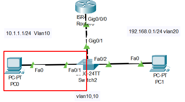
To configure a Cisco Packet Tracer project where a router connects to a switch with two VLANs (VLAN10 and VLAN20), and each VLAN has its subnet, follow these steps:
Network Design:
- Router:
- Interface:
gi0/0connected to the switch. - Sub-interfaces configured for each VLAN with IP addresses for inter-VLAN routing.
- Switch:
- VLAN10 and VLAN20 created.
- Ports assigned to each VLAN for devices on each subnet.
- The port connected to the router set as a trunk.
Step-by-Step Configuration:
1. Configure VLANs on the Switch
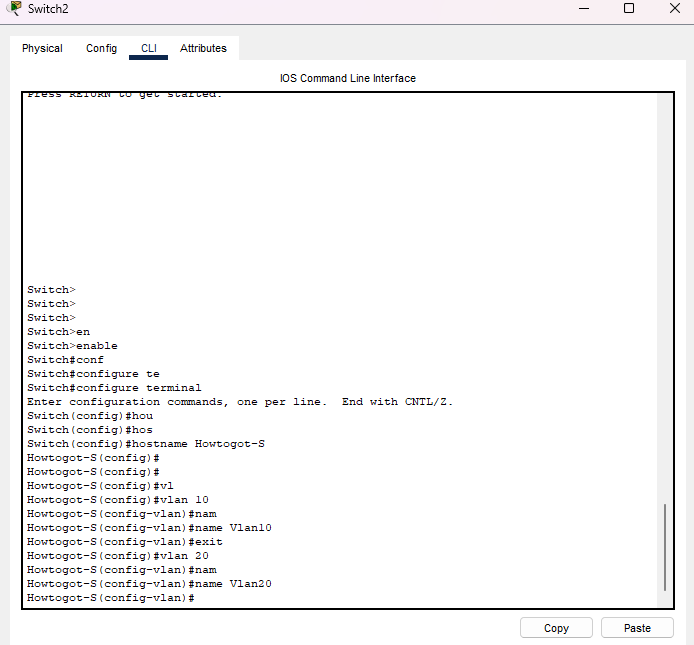
- Access the Switch CLI:
   Switch> enable
   Switch# configure terminal
   Switch(config)#hostname Howtogot-S
- Create VLAN10 and VLAN20:
   Howtogot-S(config)# vlan 10
   Howtogot-S(config-vlan)# name VLAN10
   Howtogot-S(config-vlan)# exit

   Howtogot-S(config)# vlan 20
   Howtogot-S(config-vlan)# name VLAN20
   Howtogot-S(config-vlan)# exit
Example as below:
- Assign Ports to VLANs (assuming you have two clients, one for each VLAN):
   Howtogot-S(config)# interface fa0/1
   Howtogot-S(config-if)# switchport mode access
   Howtogot-S(config-if)# switchport access vlan 10
   Howtogot-S(config-if)#no shutdown
   Howtogot-S(config-if)#do wr
   Howtogot-S(config-if)# exit

   Howtogot-S(config)# interface fa0/2
   Howtogot-S(config-if)# switchport mode access
   Howtogot-S(config-if)# switchport access vlan 20
   Howtogot-S(config-if)#no shutdown
   Howtogot-S(config-if)#do wr
Howtogot-S(config-if)# exit- Configure Trunk Port on the switch to connect to the router:
Howtogot-S(config)# interface gi0/1
Howtogot-S(config-if)# switchport mode trunk
Howtogot-S(config-if)#no shutdown
Howtogot-S(config-if)#do wr
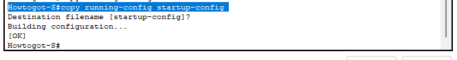
Howtogot-S(config-if)# exitSave all configuration
Howtogot-S#copy running-config startup-config
2. Configure the Router
- Access the Router CLI:
   Router> enable
   Router# configure terminal
Router(config)#hostname Howtogot-R- Configure Sub-interfaces for Each VLAN:
- On the router’s
gi0/0interface, create sub-interfaces for VLAN10 and VLAN20, assign them IP addresses, and encapsulate each with the appropriate VLAN ID.
   Howtogot-R(config)# interface gi0/0.10
   Howtogot-R(config-subif)# encapsulation dot1Q 10
   Howtogot-R(config-subif)# ip address 10.1.1.1 255.255.255.0
   Howtogot-R(config-subif)#description Vlan10
   Howtogot-R(config-subif)# do wr
   Howtogot-R(config-subif)# exit

   Howtogot-R(config)# interface gi0/0.20
   Howtogot-R(config-subif)# encapsulation dot1Q 20
   Howtogot-R(config-subif)# ip address 192.168.0.1 255.255.255.0
   Howtogot-R(config-subif)#description Vlan20
   Howtogot-R(config-subif)# do wr
Howtogot-R(config-subif)# exit- Enable the Router Interface:
   Howtogot-R(config)# interface gi0/0
   Howtogot-R(config-if)# no shutdown
   Howtogot-R(config-if)# exit
3. Configure Static IP Addresses for Clients
- Connect a PC to
fa0/1for VLAN10 and another PC tofa0/2for VLAN20.
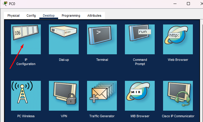
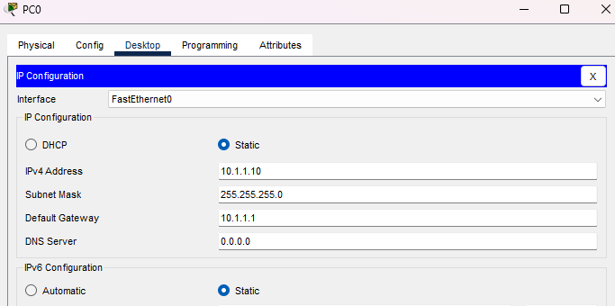
- PC in VLAN10: Assign IP Address to PC
- IP Address:
10.1.1.X(e.g.,10.1.1.10) - Subnet Mask:
255.255.255.0 - Default Gateway:
10.1.1.1
- PC in VLAN20:
For the PC2 in VLAN20, you can follow steps 1 in VLAN10
- IP Address:
192.168.0.X(e.g.,192.168.0.10) - Subnet Mask:
255.255.255.0 - Default Gateway:
192.168.0.1
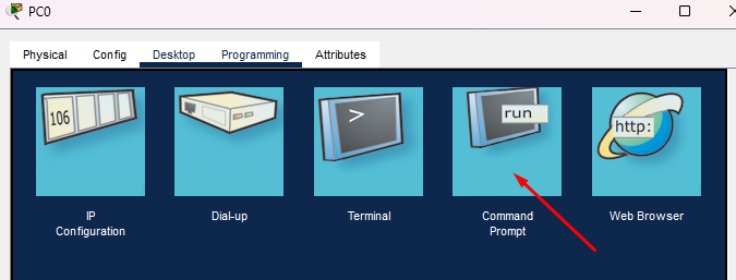
4. Test Connectivity
- Use the
pingcommand from each PC to test connectivity with its VLAN gateway. - Ensure PCs in VLAN10 and VLAN20 cannot communicate directly but can reach the router’s respective sub-interface IP addresses for inter-VLAN routing, if configured.
After assigning the IP Address you should ping test to make sure it working or not
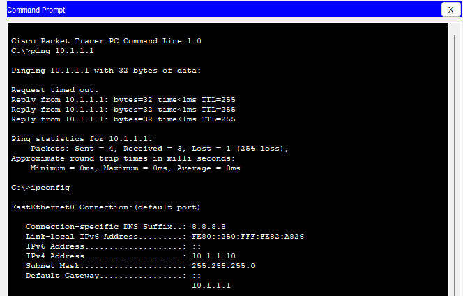
This setup enables clients in VLAN10 and VLAN20 to access their designated networks with static IP addresses. You can now ping as well. Learn more…