Configuring DHCP on a Cisco router in Packet Tracer is an essential skill for network students, as it automates IP address assignment, making network management more efficient. In this step-by-step guide, we’ll set up DHCP on a router to provide automatic IP addresses to client PCs connected via a switch. Our setup includes a router (Router0) configured to act as a DHCP server, a switch (Switch01) for connectivity, and two client PCs (PC0 and PC1). The router will use the 192.168.1.0/24 network to allocate IP addresses.
Let’s dive into the configuration!
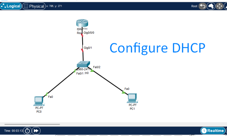
Network Setup and Configuration Plan
- Router (Router0): This device will be configured to provide DHCP.
- Router Interface (Gi0/0): Connected to Switch01 (IP address range 192.168.1.0/24).
- Switch (Switch01): Acts as the central device to connect PCs to the router.
- Switch Port Gi0/1: Connects to Router0 (Gi0/0).
- Switch Port Fa0/1: Connects to PC0.
- Switch Port Fa0/2: Connects to PC1.
- DHCP Scope: The router will distribute IP addresses from 192.168.1.1 to 192.168.1.254 with a /24 subnet mask.
Step-by-Step Configuration in Cisco Packet Tracer
- Connect Devices:
- Connect Router0’s Gi0/0 interface to Switch01’s Gi0/1 port using a copper straight-through cable.
- Connect PC0 to Switch01’s Fa0/1 port and PC1 to Switch01’s Fa0/2 port.
- Configure the Router (Router0):
- Select Router0, then go to the CLI tab.
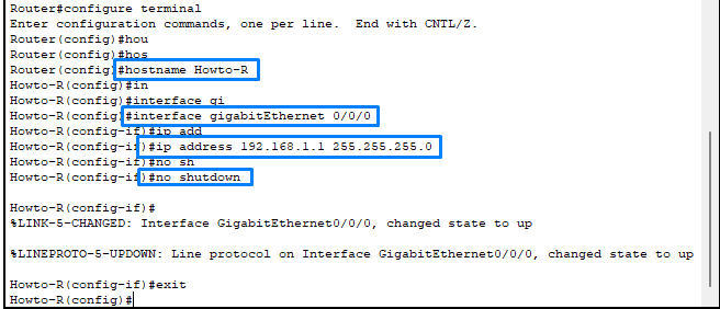
- Enter global configuration mode:
enable configure terminalSet host name on Router

- Configure Interface Gi0/0 on Router0:
- Assign an IP address to the Gi0/0 interface in the 192.168.1.0/24 network:
interface gigabitEthernet 0/0ip address 192.168.1.1 255.255.255.0no shutdownexit
- Enable DHCP on the Router:
- Define the DHCP pool and configure the IP address range:
ip dhcp pool LAN-network192.168.1.0 255.255.255.0default-router 192.168.1.1dns-server 8.8.8.8 exit- Here, we define a DHCP pool named LAN_POOL. The router will assign IP addresses within 192.168.1.0/24 and set 192.168.1.1 as the default gateway, while 8.8.8.8 is configured as the DNS server.

- Exclude the Router IP Address from the DHCP Pool (to avoid conflicts):
- Exclude 192.168.1.1 to reserve it for the router itself: Now I excluded some IP addresses to use with static Devices, the PCs will start from DHCP from 192.168.1.11
Howto-R(config)#ip dhcp excluded-address 192.168.1.1 192.168.1.10
- Verify DHCP Configuration:
- Exit configuration mode and verify DHCP setup:
show ip dhcp pool show ip dhcp binding
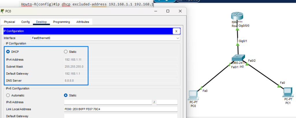
- Configure the Clients (PC0 and PC1):
- On PC0 and PC1 in Packet Tracer:
- Open the Desktop tab.
- Select IP Configuration.
- Choose DHCP for IP settings.
- After a moment, each PC should receive an IP address from the 192.168.1.0/24 range. Verify that PC0 and PC1 have IP addresses within the range, with 192.168.1.1 as the default gateway.

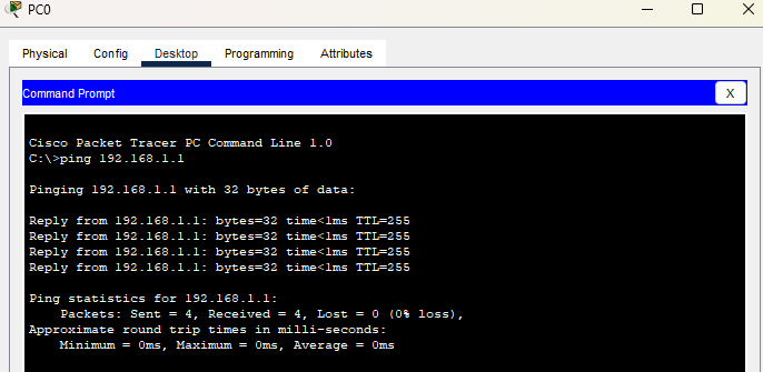
- Test Connectivity:
- On either PC0 or PC1, go to the Command Prompt in the Desktop tab.
- Test connectivity by pinging the router at 192.168.1.1:
ping 192.168.1.1 - Successful replies confirm that the DHCP configuration is working correctly, and the PCs are receiving IP addresses automatically.

This hands-on example shows how to configure DHCP on a Cisco router in Packet Tracer, making it easy to assign IP addresses to client devices on a network automatically. DHCP is a valuable tool for simplifying network management, especially in larger networks.
Note: This post How To Got shows only how to configure DHCP on a Cisco Router best on Configuration DHCP only. If you want to know clearly with full configuration can visit here with CCNA basic.
Keep exploring DHCP configurations and other networking concepts on our website to build your networking skills and become more proficient in managing complex networks!

